


Computer Aided Design
- Nov 4, 2019
- 2 min read

Using CAD software has always been a big part of robotics and engineering as a whole. This year, I’m proud to say that we have been using skills taken from our high school’s CAD courses to fully model our robot in a 3D space. The first thing we did was to divide the robot amongst the designers, this allows for the entire model to be built quicker. We use GrabCad, a community based site that allows for people to share their 3D models, to give everyone access to each others’ projects.
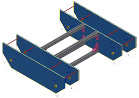
I was tasked with modelling a chassis for a mecanum drive train, a system that we’ve only just started using. The chassis is made of four 14’’ x 4’’x ⅛” plates that are connected by several T-extrusions, ultimately allowing space for the mecanum wheels to be separated from the rest of the robot. I used construction lines to represent the location and size of where the mecanum wheels are supposed to go, as the software we use has a hard time rendering the wheel files.
My second job was to begin mounting other designs, taken from the other designers, onto my chassis. This proved to be a challenge, the greater the complexity of the assembly the more likely it was for the software to crash. However, we were able to avoid this problem and create a basic construction of the entire robot. Attached to the chassis is Ryan’s elevator system and Jeremy’s claw intake. This creation allows for the team to understand what the robot would look like when built, and helped us check for any problems with our measurements.
CAD also allows us to create custom parts, for example, the aforementioned plates are being cut using a CNC router. We can do this by running the model’s file through a CAM software, in this case V-Carve, which translate the measurements into readable data for the router. Overall, I’m proud of what the team has learned about CAD software and machining over the past season, and I’m looking forward to what we will accomplish this year.


Comments